what is the emf induced in this coil while it is to the right of the origin?
Learning Objectives
Past the terminate of this section, you will be able to:
- Summate the flux of a uniform magnetic field through a loop of arbitrary orientation.
- Describe methods to produce an electromotive force (emf) with a magnetic field or magnet and a loop of wire.
The apparatus used by Faraday to demonstrate that magnetic fields can create currents is illustrated in Figure 1. When the switch is closed, a magnetic field is produced in the curlicue on the acme part of the fe ring and transmitted to the coil on the bottom role of the ring. The galvanometer is used to find whatsoever current induced in the coil on the lesser. Information technology was institute that each time the switch is airtight, the galvanometer detects a current in 1 direction in the whorl on the bottom. (You can also observe this in a physics lab.) Each time the switch is opened, the galvanometer detects a current in the reverse direction. Interestingly, if the switch remains airtight or open for any length of fourth dimension, at that place is no current through the galvanometer. Closing and opening the switch induces the current. It is the modify in magnetic field that creates the current. More basic than the current that flows is the emfthat causes it. The current is a issue of an emf induced by a irresolute magnetic field, whether or non at that place is a path for electric current to flow.
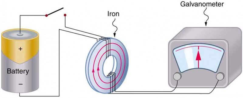
Effigy one. Faraday's appliance for demonstrating that a magnetic field can produce a current. A change in the field produced past the top coil induces an emf and, hence, a current in the bottom scroll. When the switch is opened and closed, the galvanometer registers currents in opposite directions. No current flows through the galvanometer when the switch remains airtight or open.
An experiment easily performed and oftentimes done in physics labs is illustrated in Figure 2. An emf is induced in the coil when a bar magnet is pushed in and out of it. Emfs of contrary signs are produced by movement in opposite directions, and the emfs are also reversed past reversing poles. The aforementioned results are produced if the curlicue is moved rather than the magnet—it is the relative motion that is important. The faster the motion, the greater the emf, and there is no emf when the magnet is stationary relative to the gyre.
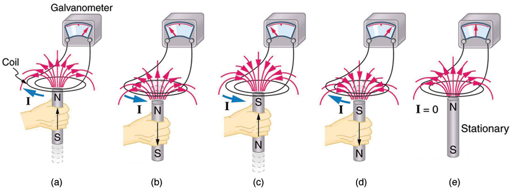
Figure two. Movement of a magnet relative to a coil produces emfs equally shown. The same emfs are produced if the scroll is moved relative to the magnet. The greater the speed, the greater the magnitude of the emf, and the emf is aught when at that place is no motion.
The method of inducing an emf used in most electric generators is shown in Figure 3. A scroll is rotated in a magnetic field, producing an alternating current emf, which depends on rotation rate and other factors that will exist explored in later sections. Note that the generator is remarkably like in construction to a motor (some other symmetry).
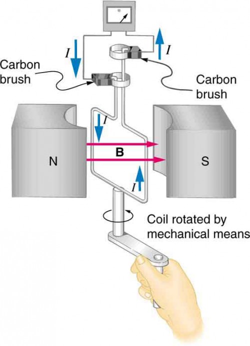
Figure 3. Rotation of a curlicue in a magnetic field produces an emf. This is the basic construction of a generator, where piece of work done to plough the coil is converted to electric free energy. Annotation the generator is very like in construction to a motor.
So nosotros come across that changing the magnitude or direction of a magnetic field produces an emf. Experiments revealed that there is a crucial quantity called the magnetic flux, Φ, given by
Φ = BA cos θ ,
where B is the magnetic field strength over an surface area A , at an angle θ with the perpendicular to the expanse as shown in Figure five. Any alter in magnetic flux Φ induces an emf. This process is defined to be electromagnetic consecration. Units of magnetic flux Φ are T ⋅ one thousandii. Equally seen in Figure 4, B cos θ = B ⊥, which is the component of B perpendicular to the surface area A . Thus magnetic flux is Φ=B ⊥ A, the production of the area and the component of the magnetic field perpendicular to it.
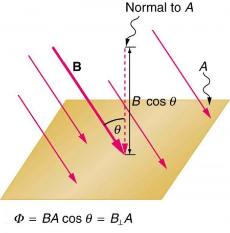
Figure 4. Magnetic flux Φ is related to the magnetic field and the expanse over which it exists. The flux Φ = BA cos θ is related to induction; whatever change in Φ induces an emf.
All consecration, including the examples given then far, arises from some change in magnetic flux Φ . For instance, Faraday changed B and hence Φ when opening and closing the switch in his apparatus (shown in Figure i). This is also true for the bar magnet and curlicue shown in Figure 2. When rotating the coil of a generator, the angle θ and, hence, Φ is inverse. Just how cracking an emf and what direction it takes depend on the alter in Φ and how chop-chop the change is fabricated, as examined in the next section.
Section Summary
- The crucial quantity in induction is magnetic flux Φ , defined to be Φ = BA cos θ , where B is the magnetic field strength over an area A at an angle θ with the perpendicular to the area.
- Units of magnetic flux Φ are T ⋅ one thousand 2 .
- Whatever modify in magnetic flux Φ induces an emf—the process is defined to be electromagnetic induction.
Conceptual Questions
1. How do the multiple-loop coils and iron ring in the version of Faraday'due south appliance shown in Effigy i enhance the observation of induced emf?
2. When a magnet is thrust into a whorl equally in Figure ii(a), what is the direction of the force exerted by the coil on the magnet? Describe a diagram showing the management of the current induced in the ringlet and the magnetic field information technology produces, to justify your response. How does the magnitude of the force depend on the resistance of the galvanometer?
3. Explain how magnetic flux tin exist zero when the magnetic field is not zero.
4. Is an emf induced in the coil in Figure 5 when it is stretched? If so, state why and give the direction of the induced current.
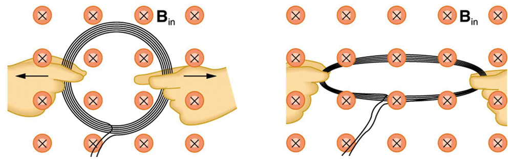
Effigy v. A circular curl of wire is stretched in a magnetic field.
Problems & Exercises
i. What is the value of the magnetic flux at ringlet ii in Figure 6 due to gyre i?
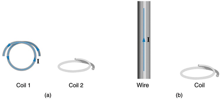
Effigy 6. (a) The planes of the 2 coils are perpendicular. (b) The wire is perpendicular to the plane of the scroll.
2. What is the value of the magnetic flux through the ringlet in Figure half dozen(b) due to the wire?
Glossary
- magnetic flux:
- the amount of magnetic field going through a item area, calculated with Φ = BA cos θ where Bis the magnetic field strength over an area Aat an bending θ with the perpendicular to the area
- electromagnetic induction:
- the process of inducing an emf (voltage) with a modify in magnetic flux
mcdonelldiferathe.blogspot.com
Source: https://courses.lumenlearning.com/physics/chapter/23-1-induced-emf-and-magnetic-flux/